
A1S38HB | MITSUBISHI floor A1S38HB
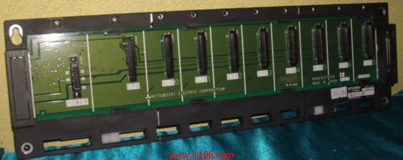
Output points: 8 points.
Output voltage and current: DC12/24V.
Output response time: 2ms.
8 point /1 a public side.
Output form: transistor output, leakage type.
24 point terminal station.
MITSUBISHI PLC protection and chain procedures.
Protection and chain is an indispensable part of the program, must be carefully considered A1S38HB.
It caan avoid the control logic confusion caused by illegal operations.
MITSUBISHI PLC initialization procedure. After MITSUBISHI PLC on power, the general need to do some of the initial operation,
In order to start making necessary preparations, to avoid the wrong operation of the system A1S38HB.
The main contents of the initialization program are: to some data area, counter and so on,
Data needed to restore some of the data area,
Set or reset some relays,
For some initial state display, etc A1S38HB MITSUBISHI A1S38HB..
MITSUBISHI PLC program simulation debugging
The basic idea of program simulation debugging is,
In order to facilitate the form of simulation to generate the actual state of the scene,
Create the necessary environmental conditions for the operation of the program MITSUBISHI A1S38HB.
Depending on the way the field signals are generated,
The simulation debugging has two forms of hardware simulation and software simulation MITSUBISHI A1S38HB. A1S68TD is a 8 channel thermocouple input module,
It can receive almost any type of thermocouple input,
Using Ans CPU A1S68TD system can meet the various requirements of process control applications,
Also has the advantages of all aspects of the ANs can provide.
The length of time required to execute the instruction, the length of the user''s program, the type of instruction, and the speed of the CPU execution are very significant,
Generally, a scanning process, the fault diagnosis time,
Communication time, input sampling and output refresh time is less,
The execution time is accounted for the vast majority of.
The response time of PLC is the interval between the time of the change of the external output signal of the PLC and the time of the change of the external output signal which is controlled by it,
Lag time, this is the time constant of the input circuit,
> The time constant of the output circuit, the arrangement of the user statement and the use of the instruction,
The cycle scan mode of PLC and the way of PLC to refresh the I/O and so on A1S38HB.
This phenomenon is called the I/O delay time effect.