
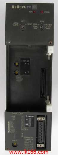
A2ACPUP21-S1 Only when the program is scanned, the new state is read MITSUBISHI A2ACPUP21-S1 CPU unit
Extension cable.
Length: 1000mm.
Input and output points: 1024 points.
Input / output data points: 1024 points.
Program capacity: 14K.
Basic command processing speed (LD command) s:0.20.
Optical data communication line.
Each scanning process. Focus on the input signal sampling A2ACPUP21-S1. Focus on the output signal to refresh.
Input refresh process. When the input port is closed,
Program in the implementation phase, the input end of a new state, the new state can not be read.
Only when the program is scanned, the new state is read A2ACPUP21-S1.
A scan cycle is divided into the input sample, the program execution, the output refresh.
The contents of the component image register are changed with the change of the execution of the program.
The length of the scan cycle is determined by the three A2ACPUP21-S1.
CPU the speed of executing instructions.
Time of instruction.
Instruction count.
Due to the adoption of centralized sampling.
Centralized output mode.
There exist input / output hysteresis phenomena, i.e., the input / output response delay MITSUBISHI A2ACPUP21-S1.
User program storage capacity: it is a measure of how much the user application can store the number of indicators.
Usually in words or K words as units. 16 bit binary number is a word,
Every 1024 words are 1K words. PLC to store instructions and data in words.
General logical operation instructions each account for 1 words MITSUBISHI A2ACPUP21-S1. Timer / counter,
Shift instruction accounted for 2 words. Data operation instructions for 2~4. Output type: transistor output, drain type.
Output points: 8 points.
OFF leakage current: 0.1mA.
Output protection function.
Rated load voltage / current: DC24V/DC24V/0 MITSUBISHI A2ACPUP21-S1.1A.
External connection: 2 wire.
Fast connector type.
Simple wiring through quick connector.
Can be installed along the 6 direction.
MITSUBISHI PLC program simulation debugging
The basic idea of program simulation debugging is,
In order to facilitate the form of simulation to generate the actual state of the scene,
Create the necessary environmental conditions for the operation of the program.
Depending on the way the field signals are generated,
The simulation debugging has two forms of hardware simulation and software simulation. DC input points: 2 points.
Input voltage and current: 7mA, DC24V.
Input response time: 10ms.
2 point /1 a public side.
Positive pole sharing.
Output points: 2 points.
Output voltage and current: DC24V.
Output response time: 2ms.
2 point /1 a public side.
Output form: transistor output, leakage type.
16 point terminal station.
MITSUBISHI PLC protection and chain procedures.
Protection and chain is an indispensable part of the program, must be carefully considered.
It can avoid the control logic confusion caused by illegal operations.
MITSUBISHI PLC initialization procedure. After MITSUBISHI PLC on power, the general need to do some of the initial operation,
In order to start making necessary preparations, to avoid the wrong operation of the system.
The main contents of the initialization program are: to some data area, counter and so on,
Data needed to restore some of the data area,
Set or reset some relays,
For some initial state display, etc..
MITSUBISHI PLC program simulation debugging
The basic idea of program simulation debugging is,
In order to facilitate the form of simulation to generate the actual statee of the scene,
Create the necessary environmental conditions for the operation of the program A2ACPUP21-S1.
Depending on the way the field signals are generated,
The simulation debugging has two forms of hardware simulation and software simulation.