
Home
>> Products
>> MITSUBISHI
>> A/QnA series PLC
>> Input module / output module
>> Input and output hybrid module
>> A0J2-E28DS MITSUBISHI A0J2-E28DS
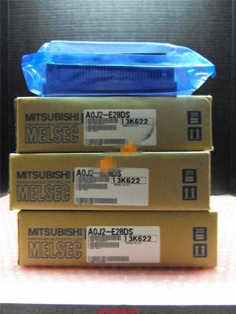
A0J2-E28DS MITSUBISHI A0J2-E28DS
Brand:
MITSUBISHI
Name: DC input / silicon controlled output module
Model: A0J2-E28DS
Input points: 16 points.
Input voltage and current: 3/7mA DC12/24V.
Input response time: 10ms.
16 point /1 a public side.
Positive pole sharing.
Output points: 12 points.
Output voltage: AC100 ~ 240V.
OFF leakage current: 3mA.
Output response time: 0.5Hz+1ms.
Output type: bidirectional thyristor output.
8 point /1 a public end, 4 points / a public end.
36 point terminal station.
With short circuit protection.
With the surge absorber.
Control solenoid valve required I/O points by the action principle of the solenoid valve can be known,
A single coil solenoid valve with PLC control to 2 input and 1 output,
A double coil solenoid valve requires 3 inputs and 2 outputs,
A button needs an input; a light sensitive switch needs 4 or 2 inputs,
A signal lamp needs 1 output, band switch,
Several bands are required for several inputs,
In general, a variety of position switches are required to take up 2 input points.
MITSUBISHI PLC is the main product in the production of MITSUBISHI motor in Dalian.
It uses a kind of programmable memory for its internal storage procedures,
Execute logic operation, sequence control, timing, counting and arithmetic operations, user oriented instruction,
And through digital or analog input / output control of various types of machinery or production process.
The number of I/O thyristor DC motor control required tube DC motor speed control system is the main form of DC speed regulation,
The thyristor rectifier unit is used to supply power to the DC motor.
PLC control of the DC drive system, the input of the PLC in addition to the main signal outside the signal,
We need to consider the switching signal, the fault signal transmission device, brake signal and fan fault signal.
The output of the PLC mainly consider the speed command signal positive 1~3 level, 1~3 level, allowing reverse switching signal and brake open signal etc..
In general, a reversible DC drive system controlled by PLC is approximately 12 input points and 8 output points,
An irreversible DC drive system requires 9 inputs and 6 output points.
...More relevant models >>>>
Name: DC input / silicon controlled output module
Model: A0J2-E28DS
Input points: 16 points.
Input voltage and current: 3/7mA DC12/24V.
Input response time: 10ms.
16 point /1 a public side.
Positive pole sharing.
Output points: 12 points.
Output voltage: AC100 ~ 240V.
OFF leakage current: 3mA.
Output response time: 0.5Hz+1ms.
Output type: bidirectional thyristor output.
8 point /1 a public end, 4 points / a public end.
36 point terminal station.
With short circuit protection.
With the surge absorber.
Control solenoid valve required I/O points by the action principle of the solenoid valve can be known,
A single coil solenoid valve with PLC control to 2 input and 1 output,
A double coil solenoid valve requires 3 inputs and 2 outputs,
A button needs an input; a light sensitive switch needs 4 or 2 inputs,
A signal lamp needs 1 output, band switch,
Several bands are required for several inputs,
In general, a variety of position switches are required to take up 2 input points.
MITSUBISHI PLC is the main product in the production of MITSUBISHI motor in Dalian.
It uses a kind of programmable memory for its internal storage procedures,
Execute logic operation, sequence control, timing, counting and arithmetic operations, user oriented instruction,
And through digital or analog input / output control of various types of machinery or production process.
The number of I/O thyristor DC motor control required tube DC motor speed control system is the main form of DC speed regulation,
The thyristor rectifier unit is used to supply power to the DC motor.
PLC control of the DC drive system, the input of the PLC in addition to the main signal outside the signal,
We need to consider the switching signal, the fault signal transmission device, brake signal and fan fault signal.
The output of the PLC mainly consider the speed command signal positive 1~3 level, 1~3 level, allowing reverse switching signal and brake open signal etc..
In general, a reversible DC drive system controlled by PLC is approximately 12 input points and 8 output points,
An irreversible DC drive system requires 9 inputs and 6 output points.
Category: slave station.
Transfer speed: 125kbps/250kbps/500kbps/1Mbps.
Transmission line form: bus system.
Total distance: 125kbps:1000m/250kbps:800m/500kbps:480m/1Mbps:240m.
The maximum connection units: 32.
Total points: input + output <=2048 point.
MITSUBISHI PLC detection, fault diagnosis and display and other procedures MITSUBISHI A0J2-E28DS.
These procedures are relatively independent, generally in the basic completion of the program design and then add A0J2-E28DS
MITSUBISHI PLC protection and chain procedures.
Protection and chain is an indispensable part of the program, must be carefully considered.
It can avoid the control logic confusion caused by illegal operations. Master / local station.
QnACPU use.
According to the control requirements of the system, using the appropriate design method to design MITSUBISHI PLC program MITSUBISHI A0J2-E28DS.
Procedures to meet the requirements of system control as the main line,
Write one by one to achieve the control function or the sub task of the program,
Gradually improve the functions specified by the system.
MITSUBISHI PLC initialization procedure. After MITSUBISHI PLC on power, the general need to do some of the initial operation,
In order to start making necessary preparations, to avoid the wrong operation of the system MITSUBISHI A0J2-E28DS.
The main contents of the initialization program are: to some data area, counter and so on,
Data needed to restore some of the data area,
Set or reset some relays,
For some initial state display, etc.. "8 slots.
Power supply unit.
QnA series unit installation.
High speed access.
CE logo fit.
I/O points is an important indicator of PLC.
Reasonable selection of I/O points can not only satisfy the control requirements of the system,
And the total investment of the system is the lowest.
The input and output points and types of PLC should be determined according to the analog quantity and switch quantity of the controlled object,
Generally an input / output element to take up an input / output point.
Taking into account the future adjustment and expansion,
In general should be estimated on the total number of points plus the amount of spare 20%~30%.
When the programmer input programinto the user program memory,
Then CPU according to the function of the system (the system program memory to explain the compiler),
Translate the user program into PLC internally recognized by the user to compile the program.
Relay output interface circuit of PLC
Working process: when the internal circuit output digital signal 1,
There is a current flowing through, the relay coil has a current, and then the normally open contact is closed,
Provide looad current and voltage A0J2-E28DS.
When the internal circuit outputs a digital signal 0, there is no current flowing through it,
The relay coil does not have a current, and the normally open contact is broken off,
A current or voltage that is discoonnected from the load A0J2-E28DS.
It is through the output interface circuit to the internal digital circuit into a signal to make the load action or not action.
...More relevant models >>>>
 Last one: MITSUBISHI AC input / silicon controlled output module A0J2-E56AS
 next one: MITSUBISHI DC input / silicon controlled output module A0J2-E56DS
Related download