
Home
>> Products
>> MITSUBISHI
>> Ans/QnAs series PLC
>> Bottom plate / expansion floor / extension cable
>> A1S32B MITSUBISHI A1S32B
A1S32B MITSUBISHI A1S32B
Brand:
MITSUBISHI
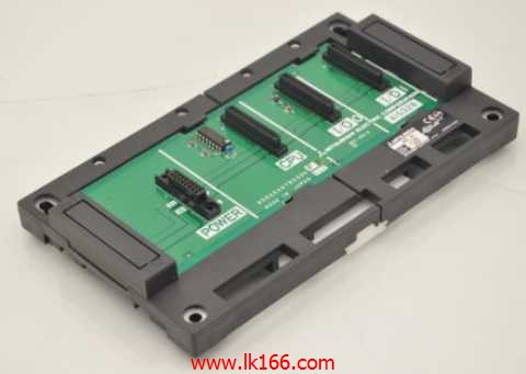
Name: CPU base plate
Model: A1S32B
I/O slots: 2 slots.
Outline dimension: 220*130.
CPU basic board can be plugged into 1 power modules,
1 CPU components and a maximum of 2, 3, 5, or 8 single slot size special function components and I/O components are respectively inserted and arranged.
The expansion port are arranged on the basic substrate on both sides, for connecting board for expansion.
Up to 3 extension substrates.
...More relevant models >>>>
Name: CPU base plate
Model: A1S32B
I/O slots: 2 slots.
Outline dimension: 220*130.
CPU basic board can be plugged into 1 power modules,
1 CPU components and a maximum of 2, 3, 5, or 8 single slot size special function components and I/O components are respectively inserted and arranged.
The expansion port are arranged on the basic substrate on both sides, for connecting board for expansion.
Up to 3 extension substrates.
3C-2V/5C-2V coaxial cable single bus remote I/O network (remote I/O station).
Q mode.
When the programmer input programinto the user program memory,
Then CPU according to the function of the system (the system program memory to explain the compiler),
Translate the user program into PLC internally recognized by the user to compile the program MITSUBISHI A1S32B.
Input status and input information input from the input interface,
CPU will be stored in the working data memory or in the input image register A1S32B
And then combine the data and the program with CPU.
The result is stored in the output image register or the working data memory,
And then output to the output interface, control the external drive.
Semiconductor circuit with memory function MITSUBISHI A1S32B.
System program memory and user memory.
System program memory for storing system program,
Including management procedures, monitoring procedures, as well as the user program to do the compiler to compile the process of interpretation.
Read only memory. Manufacturers use, content can not be changed, power does not disappear.
User memory: user program storage area and work data storage area MITSUBISHI A1S32B.
Composed of random access memory (RAM). User use.
Power cut off. Commonly used efficient lithium battery as a backup power supply, life is generally 3~5 years. Ethernet network module 10BASE-T / 10BASE5.Type of input: DC leakage.
Input points: 32 points.
Input voltage: 12/24.
Input current: 3/7mA.
Connection mode: terminal row.
Common common point: 32.
Functional block diagram language is a kind of PLC programming language, which is similar to digital logic circuit.
The function module is used to represent the function of the module,
Different function modules have different functions.
Functional module figure programming language features: functional block diagram programming language is characterized by a functional module for the unit,
Analysis and understanding of the coontrol scheme is simple and easy: function module is to use graphical form of expression,
Intuitive, for a digital logic circuit based on the design of the staff is very easy to master the programming;
Control system with complex scale and coomplex control logic,
Because the function module diagram can clearly express the function relation, the programming debugging time is greatly reduced A1S32B A1S32B.
...More relevant models >>>>
 Last one:
  next one:
 Related download