
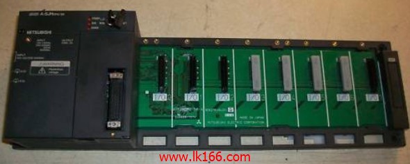
MITSUBISHI A1SJHCPU-S8 MITSUBISHI A1SJHCPU-S8
Analog channel: 8 channels.
Input / output (resolution): 0 ~ 4000.
Conversion speed: 100ms/8 channel.
Analog module installation.
Power supply: AC170V ~ 264V.
According to the control requirements of the system, using the appropriate design method to design MITSUBISHI PLC program A1SJHCPU-S8.
Procedures to meet the requirements of system control as thee main line,
Write one by one to achieve the control function or the sub task of the program,
Gradually improve the functions specified by the system A1SJHCPU-S8.
MITSUBISHI PLC detection, fault diagnosis and display and other procedures.
These procedures are relatively independent, generally in the basic completion of the program design and then add.
Hardware simulation method is to use a number of hardware equipment to simulate the generation of the signal,
The signals are connected to the input end of the PLC system in a hard wired way, and the timeliness is strong A1SJHCPU-S8.
Software simulation method is in the MITSUBISHI PLC in the preparation of a set of simulation program,
The simulation provides the field signal, which is simple and easy to operate, but it is not easy to guarantee the timeliness MITSUBISHI A1SJHCPU-S8.
Simulation of the process of debugging, debugging method can be used to segment, and the monitoring function of programmer.
RS-232 1 channels.
With DC input 2 points.
Transistor output 2.
Number of stations: 1 stops MITSUBISHI A1SJHCPU-S8.
Station type: intelligent equipment station.
MITSUBISHI PLC online debugging.
On-line debugging is the process that will through the simulation debugging to further carry on the on-line unification to adjust.
On-line debugging process should be step by step,
From MITSUBISHI PLC only connected to the input device, and then connect the output device, and then connect to the actual load and so on and so on step by step MITSUBISHI A1SJHCPU-S8.
If you do not meet the requirements, the hardware and procedures for adjustment.
Usually only need to modify the part of the program can be.
MITSUBISHI PLC hardware implementation
Hardware implementation is mainly for the control cabinet and other hardware design and field construction.
Design control cabinet and the operating table and other parts of the electrical wiring diagram and wiring diagram.
Electrical interconnection diagram of each part of the design system.
According to the constructioon drawings of the site wiring, and carry out a detailed inspection A1SJHCPU-S8.
Because the program design and hardware implementation can be carried out at the same time,
So the design cycle of the MITSUBISHI PLC control system can be greatly reduced.