
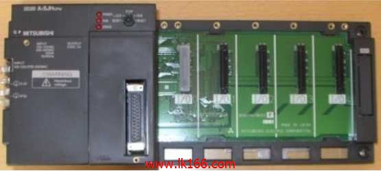
A1SJHCPU Memory capacity: bytes 64K MITSUBISHI A1SJHCPU CPU component
QCPU (Q mode) bus connection.
2 joint.
Applicable models: A985 (-V) /975/970/960/956 (W) GOT. 10BASE5.
For Q mode.
Control layer /MELSECNET/10 (H) is the middle layer of the whole network system,
Control network which is convenient and high speed processing data transmission between PLC, CNC and other control equipment A1SJHCPU.
As MELSEC control network MELSECNET/10,
With its good real-time performance, simple network settings, no procedures of the network data sharing concept,
As well as the redundant circuit and so on, has obtained the very high market appraisal,
The number of devices to reach the highest in japan,
In the world is also one of the few A1SJHCPU.
And MELSECNET/H not only inherited the excellent characteristics of MELSECNET/10,
Also makes the network real-time better, more data capacity,
Further adapt to the needs of the market A1SJHCPU.
I/O control method: refresh mode or direct mode.
User program storage capacity: 8K step.
I/O points: 256 points.
Memory capacity: bytes 64K.
ANSCPU has been updated to ANSHCPU, and it has the following advantages MITSUBISHI A1SJHCPU.
16 bit dedicated microprocessor.
Large capacity battery backup memory RAM.
Extended I/O control capability.
Dedicated CC-Link instruction.
Capacity for extended comment storage.
Write speed processing. 8 slots.
Power supply unit.
QnA series unit installation MITSUBISHI A1SJHCPU.
High speed access.
CE logo fit.
I/O points is an important indicator of PLC.
Reasonable selection of I/O points can not only satisfy the control requirements of the system,
And the total investment of the system is the lowest.
The input and output points and types of PLC should be determined according to the analog quantity and switch quantity of the controlled object,
Generally an input / output element to take up an input / output point MITSUBISHI A1SJHCPU.
Taking into account the future adjustment and expansion,
In general should be estimated on the total number of points plus the amount of spare 20%~30%.
When the programmer input programinto the user program memory,
Then CPU according to the function of the system (the system program memory to explain the compiler),
Translate the user program into PLC internally recognized by the user to compile the program.
Relay output interface circuit of PLC
Working process: when the internal circuit output digital signal 1,
There is a current flowing through, the relay coil has a current, and then the normally open contact is closed,
Provide load current and voltage.
When the internal circuit outputs a digital signal 0, there is no current flowing through it,
The relay coil does not have a current, and the normally open contact is broken off,
A current or voltage that is disconnected from the load A1SJHCPU.
It is through the output interface circuit to the internal digital circuit into a signal to make the load action or not action.