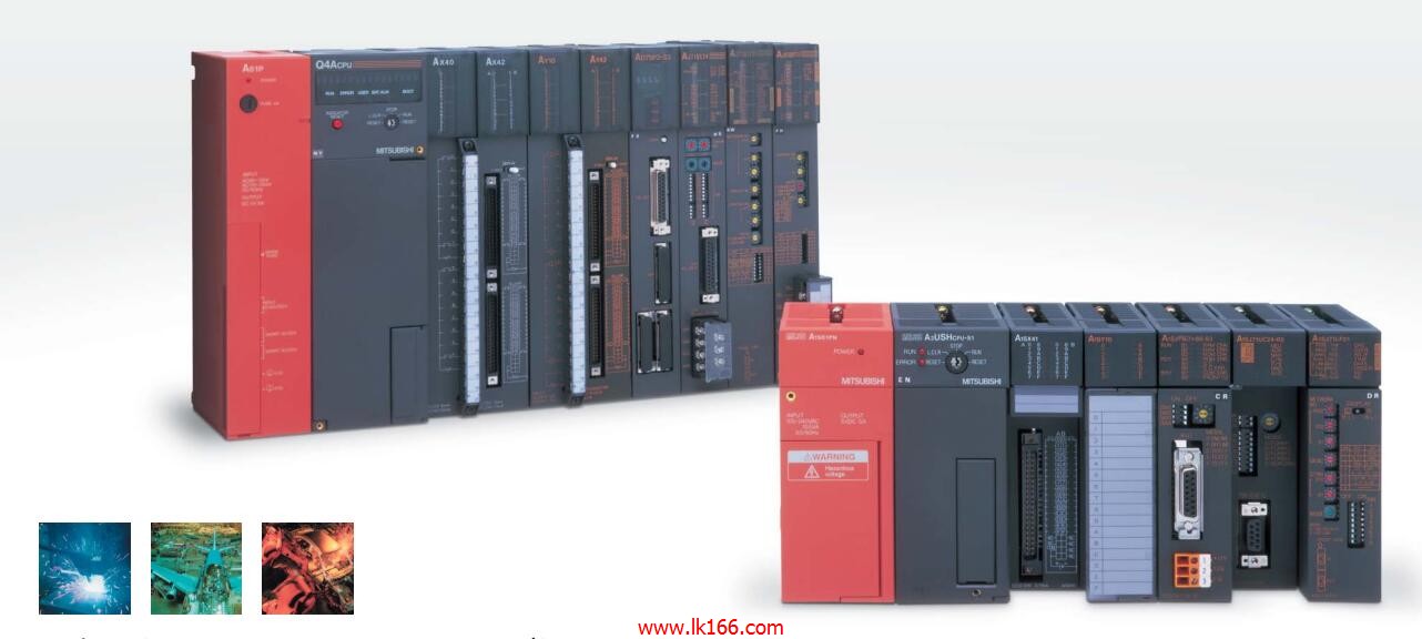
A0J2-C214-S1 How to determine the input / output device of MITSUBISHI plc MITSUBISHI A0J2-C214-S1 Computer connection module

RS-232:1 channel, RS-422:1 channel.
BASIC program mode (A3MCPU corresponding): BASIC console interface to use.
Sequential program mode (program controller CPU correspondence): non sequential computer connection interface and use.
How to choose MITSUBISHI PLC.
MITSUBISHI PLC options include the choice of MITSUBISHI PLC models, capacity, I/O module, power, etc A0J2-C2114-S1..
MITSUBISHI PLC distribution I/O points and design MITSUBISHI PLC peripheral hardware circuit
Draw the I/O point of the PLC and the input / output device connection diagram or the corresponding table,
This part also can be carried out in second steps A0J2-C214-S1.
Design PLC peripheral hardware circuit.
Draw the electrical wiring diagram of the other parts of the system,
Including the main circuit and the control circuit does not enter the PLC, etc A0J2-C214-S1..
The electrical schematic diagram of the system composed of I/O PLC connection diagram and PLC peripheral electrical circuit diagram.
So far the system''s hardware electrical circuit has been determined. Cable length: 6 meters
Extending cable to connect CPU main substrate and extended substrate,
According to the model can provide different cable length,
If you need to connect the AnN type expansion substrate is required,
Selection of A1SC05NB (A1SC07NB) cable MITSUBISHI A0J2-C214-S1.
RS-232C 1 channel, RS-422 1 channel.
Transfer speed: 0 MITSUBISHI A0J2-C214-S1.3-19.2kbps.
Multi station communication network function (Master / local station).
How to determine the input / output device of MITSUBISHI plc.
According to the control requirements of the system,
All input devices and output devices required for the determination of the system,
To determine the input / output device related to the MITSUBISHI PLC,
To determine the I/O PLC points MITSUBISHI A0J2-C214-S1.
Detailed analysis of the process and work characteristics of the controlled object,
To understand the coordination between the controlled object machine, electricity and liquid,
The control requirements of the controlled object for MITSUBISHI PLC control system are put forward,
Determine the control program, to develop a design task book. Output type: transistor drain.
Output points: 16 points.
Load voltage: DC24.
Load current: 2A.
Connection mode: terminal row.
Common public end points: 8.
Switching value, also known as logic, refers to only two values, 0 or 1, ON or OFF.
It is the most common control, it is the advantage of PLC control,
Is also the most basic application of PLC.
Switch volume control is designed to,
According to the current input combination of the switch quantity and the history of the input sequence,
So that PLC generates the corresponding switching output,
In order to make the ssystem work in a certain order A0J2-C214-S1.
So, sometimes also known as the order control.
And sequential control is divided into manual, semi-automatic or automatic.
And the control principle is decentralized, centralized and hybrid control three.
