
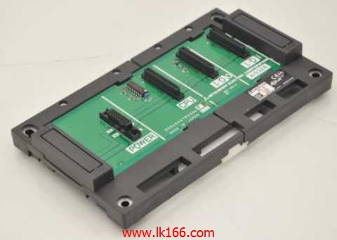
A1S32B MITSUBISHI CPU base plate MITSUBISHI A1S32B
Optional features of memory card (A/FX compatible).
Non extended memory.
Applicable models: A985 (-V) /975/970/A960GOT (-B) /A956WGOT. Series Name: A951GOT.
Size: 6 inches.
Resolution: 320 * 240.
Display device: STN color display.
Display color: 8 color.
Power supply: DC24V A1S32B.
Built in QnA/A communication interface.
Memory card:: 3M.
China is the world''s biggest market for human machine interface,
But it is not the highest sales market in the world,
This shows that the low-end user interface in China has a large share of A1S32B.
In recent years, the rapid development of national brands, to take a low price and other strategies, is a massive attack on the low end of the market,
Has occupied the dominant position in the low-end market, has won the recognition of the majority of users A1S32B.
International brands are also gradually developing its economic products, in order to seize the share of the low-end market.
Therefore, in the low-end market steady,
The overall performance of the domestic human machine interface manufacturers showing a rapid growth of the state MITSUBISHI A1S32B.
I/O slots: 2 slots.
Outline dimension: 220*130.
CPU basic board can be plugged into 1 power modules,
1 CPU components and a maximum of 2, 3, 5, or 8 single slot size special function components and I/O components are respectively inserted and arranged MITSUBISHI A1S32B.
The expansion port are arranged on the basic substrate on both sides, for connecting board for expansion.
Up to 3 extension substrates. RS-232:1 channel, RS-422:1 channel.
BASIC program mode (A3MCPU corresponding): BASIC console interface to use.
Sequential program mode (program controller CPU correspondence): non sequential computer connection interface and use MITSUBISHI A1S32B.
How to choose MITSUBISHI PLC.
MITSUBISHI PLC options include the choice of MITSUBISHI PLC models, capacity, I/O module, power, etc..
MITSUBISHI PLC distribution I/O points and design MITSUBISHI PLC peripheral hardware circuit
Draw the I/O point of the PLC and the input / output device connection diagram or the corresponding table,
This part also can be carried out in second steps.
Design PLC peripheral hardware circuit.
Draw the electrical wiring diagram of the other parts of the system,
Including the main circuit and the control circuit does not enter the PLC, etc A1S32B..
The electrical schematic diagram of the system composed of I/O PLC connection diagram and PLC peripheral electrical circuit diagram.
So far the system''s hardware electrical circuit has been determined.