
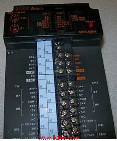
AD61C How to determine the input / output device of MITSUBISHI plc MITSUBISHI AD61C
Input type: DC input, positive common end.
Input points: 32 points.
Enter the response time: 1.5ms the following.
Rated input voltage / current: DC24V/5mA.
External connection: 3 wire.
Sensor connector type (E-CON type).
Using industry standard E-CON type.
Simple wiring through sensor connector AD61C.
When installing the module can choose to use the DIN guide rail or screw mounting.
3 wire sensor input.
2 channels.
50kpps.
Count input signal: DC5/12/24V.
External input: DC5/12/24V AD61C.
Output: Transistor (open collector) 0.5A DC12/24V.
Output: DC12/24V, 0.3A.
47 point terminal station.
How to determine the input / output device of MITSUBISHI plc.
According to the control requirements of the system,
All input devices and output devices required for the determination of the system,
To determine the input / output device related to the MITSUBISHI PLC,
To determine the I/O PLC points AD61C.
Detailed analysis of the process and work characteristics of the controlled object,
To understand the coordination between the controlled object machine, electricity and liquid,
The control requirements of the controlled object for MITSUBISHI PLC control system are put forward,
Determine the control program, to develop a design task book MITSUBISHI AD61C. DC input points: 32 points.
Input voltage and current: 3/7mA, DC12/24V MITSUBISHI AD61C.
Response time: 10ms.
Positive pole sharing.
16 point /1 a public side.
Output points: 24 points.
Output voltage and current: DC12/24V, 0.5A/1 point, 3.2A/1 common end.
Response time: 2ms.
8 point /1 a public end, 4 point /1 a public end.
Output form: transistor output, leakage type MITSUBISHI AD61C.
36 point terminal table * 2.
Number of stations: 8 stops.
Compact remote I/O unit.
According to the control requirements of the system, using the appropriate design method to design MITSUBISHI PLC program.
Procedures to meet the requirements of system control as the main line,
Write one by one to achieve the control function or the sub task of the program,
Gradually improve the functions specified by the system.
MITSUBISHI PLC detection, fault diagnosis and display and other procedures.
These procedures are relatively independent, generally in the basic completion of the program design and then add.
Hardware simulation method is to use a number of hardware equipment to simulate the generation of the signal,
The signals are connected to the input end of the PLC system in a hard wired way, and the timeliness is strong.
Software simulation method is in the MITSUBISHI PLC in the preparation of a set of simulation program,
The ssimulation provides the field signal, which is simple and easy to operate, but it is not easy to guarantee the timeliness AD61C.
Simulation of the process of debugging, debugging method can be used to segment, and the monitoring function of programmer.