
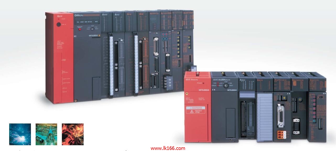
AJ71QBR11 MITSUBISHI AJ71QBR11 MITSUBISHI PLC distribution I/O points and design MITSUBISHI PLC peripheral hardware circuit Coaxial cable module
Series Name: A950GOT.
Size: 6 inches.
Resolution: 320 * 240.
Display equipment: high brightness TFT color display.
Display color: 256 color.
Power supply: DC24V.
Built in RS-422 communication interface
Memory card: 3M.
Some mechanical industries, such as machine tools, textile machinery, electronic equipment and other industries,
In the country has been developed for decades of history, relatively speaking, is relatively mature industry, in the long run,
These industries also exist the needs of equipment upgrades AJ71QBR11 AJ71QBR11.
In this upgrading process, there will be some small, has been using relatively low-end products manufacturers are eliminated,
But there are also a lot of enterprises in the process of equipment renewal,
Re positioning the needs to find those that can meet their development plans,
Equipment suppliers to help them improve their productivity AJ71QBR11. Cable length: 0.5 meters.
For the GOT and the PC card interface unit (A1SD59J-MIF) connection.
For FXCPU expansion board FX2N-422-B, FX1N-422-BD and GOT connection.
3C-2V/5C-2V coaxial cable MITSUBISHI AJ71QBR11.
Single bus.
PC inter network (management station / common station) / remote I/O network (remote control station).
How to choose MITSUBISHI PLC.
MITSUBISHI PLC options include the choice of MITSUBISHI PLC models, capacity, I/O module, power, etc..
MITSUBISHI PLC distribution I/O points and design MITSUBISHI PLC peripheral hardware circuit
Draw the I/O point of the PLC and the input / output device connection diagram or the corresponding table,
This part also can be carried out in second steps MITSUBISHI AJ71QBR11.
Design PLC peripheral hardware circuit MITSUBISHI AJ71QBR11.
Draw the electrical wiring diagram of the other parts of the system,
Including the main circuit and the control circuit does not enter the PLC, etc..
The electrical schematic diagram of the system composed of I/O PLC connection diagram and PLC peripheral electrical circuit diagram.
So far the system''s hardware electrical circuit has been determined. Category: slave station.
Transfer speed: 125kbps/250kbps/500kbps/1Mbps.
Transmission line form: bus system.
Total distance: 125kbps:1000m/250kbps:800m/500kbps:480m/1Mbps:240m.
The maximum connection units: 32.
Total points: input + output <=2048 point.
MITSUBISHI PLC detection, fault diagnosis and display and other procedures.
These procedures are relatively independent, generally in the basic completion of the proggram design and then add AJ71QBR11.
MITSUBISHI PLC protection and chain procedures.
Protection and chain is an indispensable part of the program, must be carefully considered.
It can avoid the control logic confusion caused by illegal operations.