
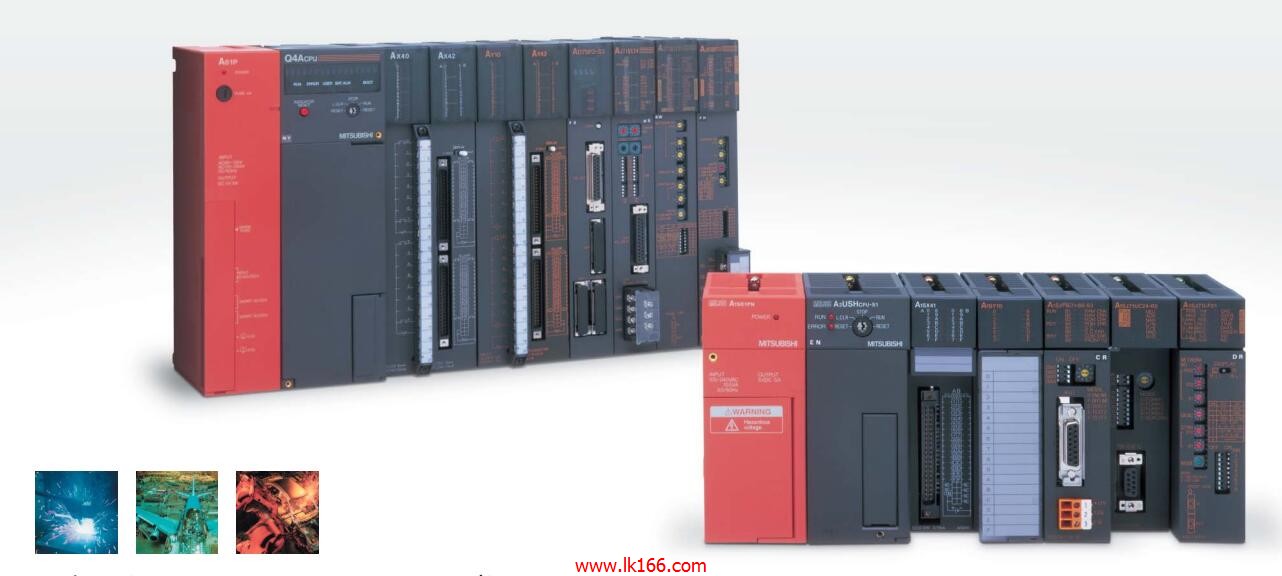
AJ72QLP25 SI/QSI fiber optic cable module MITSUBISHI AJ72QLP25
Analog channel: 8 channels.
Input / output (resolution): 0 ~ 4000.
Conversion speed: 100ms/8 channel.
Analog module installation.
Power supply: AC85 ~ 132V.
According to the control requirements of the system, using the appropriate design method to design MITSUBISHI PLC program AJ72QLP25.
Procedures to meet the requirements of system control as the main line,
Write one by one to achieve the control function or the sub task of the program,
Gradually improve the functions specified by the system AJ72QLP25.
MITSUBISHI PLC detection, fault diagnosis and display and other procedures.
These procedures are relatively independent, generally in the basic completion of the program design and then add.
Hardware simulation method is to use a number of hardware equipment to simulate the generation of the signal,
The signals are connected to the input end of the PLC system in a hard wired way, and the timeliness is strong AJ72QLP25.
Software simulation method is in the MITSUBISHI PLC in the preparation of a set of simulation program,
The simulation provides the field signal, which is simple and easy to operate, but it is not easy to guarantee the timeliness MITSUBISHI AJ72QLP25.
Simulation of the process of debugging, debugging method can be used to segment, and the monitoring function of programmer.
SI/QSI/H-PCF/ wide range H-PCF fiber optic cable.
Double loop.
Remote I/O network (remote control station) MITSUBISHI AJ72QLP25.
How to choose MITSUBISHI PLC.
MITSUBISHI PLC options include the choice of MITSUBISHI PLC models, capacity, I/O module, power, etc..
MITSUBISHI PLC distribution I/O points and design MITSUBISHI PLC peripheral hardware circuit
Draw the I/O point of the PLC and the input / output device connection diagram or the corresponding table,
This part also can be carried out in second steps MITSUBISHI AJ72QLP25.
Design PLC peripheral hardware circuit.
Draw the electrical wiring diagram of the other parts of the system,
Including the main circuit and the control circuit does not enter the PLC, etc..
The electrical schematic diagram of the system composed of I/O PLC connection diagram and PLC peripheral electrical circuit diagram.
So far the system''s hardware electrical circuit has been determined. CPU:A3UCPU PLC is the same.
PLC program capacity: 30K step.
I/O points: 2084 points.
Processing speed (sequential order): 0.15 s/ step.
Control axis: up to 32.
Servo program capacity: 14K step.
Servo amplifier: SSCNET connected external servo amplifier.
PLC selection with the development of PLC technology, more and more types of PLC products,
Function is becoming more and more perfect, and its application is more and more extensive.
Different series of different models of PLC has different performance, applicable occcasions also have different emphasis,
Price also has a greater difference AJ72QLP25. Therefore PLC selection,
Under the premise of meeting the control requirements,
Should consider the best performance to price ratio, a reasonable choice of PLC.