
MITSUBISHI AX81-S2 Input module AX81-S2
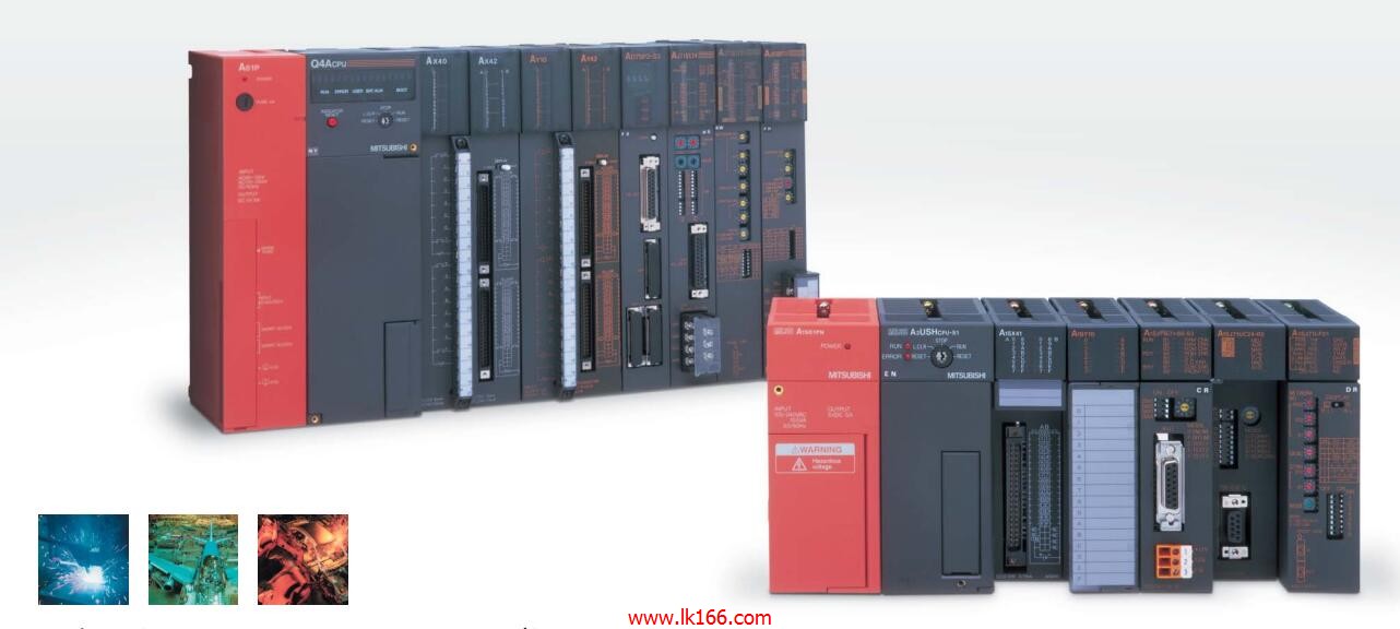
2 channels.
200/10kpps.
Count input signal: RS-422-A (gap dynamic appearance of rye).
External input: RS-422-A (gap dynamic appearance rye).
Compare output: transistor DC12/24V, 0.5A/1 point, 2A/1 common.
20 point terminal station.
Structured text language is a programming language that describes a program with a structured description of the text AX81-S2..
It is a programming language similar to a high level language. In large and medium
Structured text is often used to describe the relationship between the various variables in the control system based on the PLC system AX81-S2.
Mainly used for other programming languages more difficult to achieve the user program.
Sequential function flow chart language is designed to satisfy the sequential logic control.
The process of sequential process action is divided into steps and transformation conditions,
According to the transfer condition, the control system is distributed in the function flow sequence,
Step by step according to the sequence of actions AX81-S2.
Each step represents a control function, represented by the box MITSUBISHI AX81-S2.
In the box, the ladder logic is used to complete the task of the corresponding control function.
This programming language makes the program structure clear and easy to read and maintain,
Greatly reduce the programming workload, shorten the programming and debugging time MITSUBISHI AX81-S2.
Used in the system of the size of the school, procedures for more complex occasions.
Sequence function flow chart programming language features: to function as the main line, in accordance with the functional flow of the order of distribution, clear, easy to understand the user program,
Avoid the defect of ladder diagram or other languages,
At the same time, the use of ladder language to avoid the use of ladder programming,
Due to the complicated mechanical interlock, the structure of the user program is complex and difficult to understand,
User program scan time is also greatly reduced MITSUBISHI AX81-S2. 5 slots.
Can be installed in the power supply unit for A series units installed QnA/.
When the programmer input programinto the user program memory,
Then CPU according to the function of the system (the system program memory to explain the compiler),
Translate the user program into PLC internally recognized by the user to compile the program.
Relay output interface circuit of PLC
Working process: when the internal circuit output digital signal 1,
There is a current flowing through, the relay coil has a current, and then the normally open contact is closed,
Provide load current and voltage.
When the internal circuit outputs a digital signal 0, there is no current flowing through it,
The relay coil does not have a current, and the normally open contact is broken off,
A current or voltage that is disconnected from the load.
It is through the output interface circuit to the internal digital circuit into a signal to make the load action or not action.
I/O points is an important indicator of PLC.
Reasonable selection of I/O points can not only satisfy the control requirements of the system,
And the total investment of the system is the lowest.
The input and output points and types of PLC should be determined according to the analog quantity and switch quantity of the controlled object,
Generally an input / output element to take up an input / output point.
Taking into account the future adjustment and expansion,
In general should be estimated on the total number of points plus the amount of spare 20%~30%.
The following describes the centralized control system I/O points of the estimate.
Input points: 32 points.
Voltage: DC48/60V.
Current: 3/4mA.
Response time: 20ms.
8 points / a common end.
Negative utility.
38 point terminal station.
Each scanning process. Focus on the input signal sampling. Focus on the output signal to refresh.
Input refresh process. When the input port is closed,
Program in the implementation phase, the input end of a new state, the new state can not be read.
Only when the program is scanned, the new state is read.
A scan cycle is divided into the input sample, the program execution, the output refresh.
The contents of the component image register are changed with the change of the execution of the program.
The length of the scan cycle is determined by the three.
CPU the speed of executing instructions.
Time of instruction.
Instruction count.
Due to the adoption of centralized sampling.
Centralized output mode.
There exist input / output hysteresis phenomena, i.e., the input / output response delay.
PLC selection with the development of PLC technology, more and more types of PLC products,
Function is becoming more and more perfect, and its application is more and more extensive.
Different series of different models of PLC has different performance, applicable occasions also have different emphasis,
Price also has a greater difference. Therefore PLC selection,
Under the premise of meeting the control requirements,
Should consider the best performance to price ratio, a reasonable choice of PLC.
System program memory for storing system proggram,
Including management procedures, monitoring procedures, as well as the user program to do the compiler to compile the process of interpretation AX81-S2.
Read only memory. Manufacturers use, content can not be changed, power does not disappear.