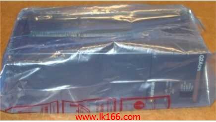
Q2ACPU MITSUBISHI Q2ACPU The photoelectric coupler is composed of two luminous two extreme tubes and a photoelectric transistor CPU unit

5 slots.
Requires 1 power modules.
Used to install the old section of the large A series PLC module.
Switch volume control is designed to,
According to the current input combination of the switch quantity and the history of the input sequence,
So that PLC generates the corresponding switching output,
In order to make the system work in a certain order Q2ACPPU.
So, sometimes also known as the order control.
And sequential control is divided into manual, semi-automatic or automatic.
And the control principle is decentralized, centralized and hybrid control three Q2ACPU.
Each scanning process. Focus on the input signal sampling. Focus on the output signal to refresh.
Input refresh process. When the input port is closed,
Program in the implementation phase, the input end of a new state, the new state can not be read Q2ACPU.
Only when the program is scanned, the new state is read.
A scan cycle is divided into the input sample, the program execution, the output refresh.
The contents of the component image register are changed with the change of the execution of the program MITSUBISHI Q2ACPU.
The length of the scan cycle is determined by the three.
CPU the speed of executing instructions.
Time of instruction.
Instruction count.
Due to the adoption of centralized sampling.
Centralized output mode.
There exist input / output hysteresis phenomena, i MITSUBISHI Q2ACPU.e., the input / output response delay.
System program memory for storing system program,
Including management procedures, monitoring procedures, as well as the user program to do the compiler to compile the process of interpretation.
Read only memory. Manufacturers use, content can not be changed, power does not disappear MITSUBISHI Q2ACPU.Input / output points: 4096 points.
You can use the CF card.
Version OS:VxWorks 5.4.
Easy connection programming tool via ethernet.
Programming tools (Works2 GX, Developer GX) and CPU direct connection (1 to 1),
No need to carry out the IP address settings. And there is no need to select the cable, the straight line and the cross line can be used.
Therefore, this connection method and the use of USB, can easily communicate with the CPU,
Even the operators are not familiar with the network settings can easily establish a connection.
Easy connection through the hub CPU.
By using an Ethernet hub, programming tools and multiple CPU can be connected simultaneously.
Through the programming tool can be searched and displayed in the list has been connected to the CPU.
Therefore, even if the IP CPU address is unknown, just choose from this list, you can easily connect.
Seamless communication without network level constraints.
With the latest high-speed, large capacity IE CC-Link controller network and IE CC-Link field network,
Corresponding to the increasing amount of information.
Together with previous MELSECNET/H, Ethernet and CC-Link,
These networks can be across the network type or level of differences, to achieve seamless communication.
Programmable logic controller on the network through the programming tool of the Ethernet connection,
Monitoring and programming.
Input and output points: 512 points.
Input / output data points: 8192 points.
Program capacity: 28k.
Basic command processing speed (LD command) S:0.2.
The length of time required to execute the instruction, the length of the user''s program, the type of instruction, and the speed of the CPU execution are very significant,
Generally, a scanning process, the fault diagnosis time,
Communication time, input sampling and output refresh time is less,
The execution time is accounted for the vast majority of.
The photoelectric coupler is composed of two luminous two extreme tubes and a photoelectric transistor.
Light emitting diode two: the input of a photo coupler and the change of electrical signal,
The light signal is generated by the light emitting diode, which is the same as the input signal.
The working process of the input interface circuit: when the switch is closed, the diode light,
The transistor is then guided to the internal circuit and input signal under the irradiation of the light.
When the switch is off, the diode does not emit light, and the transistor is not on the way. Internal circuit input signal.
It is through the input interface circuit to the external switch signal into PLC internal can accept the digital signal.
Photoelectric three levels: in the light of the light signal conduction, the degree of light signal and the intensity of the light signal.
The output signal has a linear relationship with the input signal in the linear operating region of the photoelectric coupler.
User program storage capacity: it is a measure of how much the user application can store the number of indicators.
Usually in words or K words as units. 16 bit binary number is a word,
Every 1024 words are 1K words Q2ACPU. PLC to store instructions and data in words.
General logical operation instructions each account for 1 words. Timer / counter,
Shift instruction accounted for 2 words. Data operation instructions for 2~4.
