
Home
>> Products
>> MITSUBISHI
>> Ans/QnAs series PLC
>> Output module
>> A1SY18AEU Relay output module MITSUBISHI A1SY18AEU
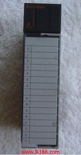
A1SY18AEU Relay output module MITSUBISHI A1SY18AEU
Brand:
MITSUBISHI
Name: Relay output module
Model: A1SY18AEU
Output type: relay.
Output points: 8 points.
Load voltage: AC240/DC24.
Load current: 2A.
Connection mode: terminal row.
Common public end points: 1.
Structured text language is a programming language that describes a program with a structured description of the text.
It is a programming language similar to a high level language. In large and medium
Structured text is often used to describe the relationship between the various variables in the control system based on the PLC system.
Mainly used for other programming languages more difficult to achieve the user program.
The structured text programming language uses the computer description method to describe the various kinds of relations between the various variables in the system,
Complete the required function or operation.
Most PLC manufacturers use structured text programming language similar to BASIC language, PASCAL language or C language and other advanced languages,
But in order to be convenient, the expression methods of the statement and the types of statements are simplified.
Structured text programming language features: the use of high-level language programming, you can complete the complex control operations,
Need to have a certain level of computer knowledge and programming skills,
Higher requirements for engineering designers. Poor visibility and operability.
...More relevant models >>>>
Name: Relay output module
Model: A1SY18AEU
Output type: relay.
Output points: 8 points.
Load voltage: AC240/DC24.
Load current: 2A.
Connection mode: terminal row.
Common public end points: 1.
Structured text language is a programming language that describes a program with a structured description of the text.
It is a programming language similar to a high level language. In large and medium
Structured text is often used to describe the relationship between the various variables in the control system based on the PLC system.
Mainly used for other programming languages more difficult to achieve the user program.
The structured text programming language uses the computer description method to describe the various kinds of relations between the various variables in the system,
Complete the required function or operation.
Most PLC manufacturers use structured text programming language similar to BASIC language, PASCAL language or C language and other advanced languages,
But in order to be convenient, the expression methods of the statement and the types of statements are simplified.
Structured text programming language features: the use of high-level language programming, you can complete the complex control operations,
Need to have a certain level of computer knowledge and programming skills,
Higher requirements for engineering designers. Poor visibility and operability.
Input type: AC.
Input points: 16 points.
Input voltage: AC100-120V.
Input current: 7mA.
Connection mode: terminal row.
Common common point: 16.
The instruction list programming language is a programming language similar to assembly language mnemonic,
As well as assembly language by the operation code and the number of operations MITSUBISHI A1SY18AEU.
In the case of the computer for the PLC handheld programmer compile user program A1SY18AEU
At the same time, the programming language of the instruction list corresponds to the ladder diagram programming language,
In PLC programming software can be converted to each other. Figure 3 is the instruction sheet corresponding to the ladder diagram of figure 2PLC.
The characteristics of instruction table programming language is used to represent mnemonic operation function,
Easy to remember, easy to grasp;
In the handheld programmer on the keyboard using the mnemonic representation, easy to operate, can be programmed in computer;
There is a one-to-one correspondence between the ladder diagram and the ladder diagram MITSUBISHI A1SY18AEU. Its characteristics are basically consistent with the ladder diagram language MITSUBISHI A1SY18AEU. Axis of control: 2 axis linkage, 2 axis independence.
Interpolation function: 2 axis linear interpolation, 2 axis arc interpolation.
A1SD75 series components show the MITSUBISHI in the manufacture and design of CNC, frequency converter,
Integrated technical experience in servo system and PLC A1SY18AEU MITSUBISHI.
These components have a wealth of features that are sufficient to meet the highest requirements in the application of positioning control A1SY18AEU MITSUBISHI.
Up to 3 axis linkage operation,
In low cost motion control applications, this component can be used to control the operation of a multi - to 3 axis, which can be used to account for only one slot. Signal transmission device B/NET interface device for power distribution control equipment
The response time of PLC is the interval between the time of the change of the external output signal of the PLC and the time of the change of the external output signal which is controlled by it,
Lag time, this is the time constant of the input circuit,
The time constant of the output circuit, the arrangement of the user statement and the use of the instruction,
The cycle scan mode of PLC and the way of PLC to refresh the I/O and so on A1SY18AEU MITSUBISHI.
This phenomenon is called the I/O delay time effect A1SY18AEU.
Input status and input information input from the input interface,
CPU will be stored in the working data memory or in the input image register.
And then combine the data and the program with CCPU MITSUBISHI A1SY18AEU.
The result is stored in the output image register or the working data memory,
And then output to the output interface, control the external drive.
...More relevant models >>>>
 Last one: MITSUBISHI Relay output module A1SY18A
 next one: MITSUBISHI Bidirectional thyristor output module A1SY22
Related download