
Home
>> Products
>> MITSUBISHI
>> Ans/QnAs series PLC
>> Input and output integrated module
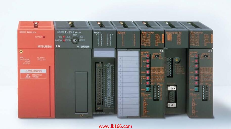
>> Input / output module A1SH42P-S1 MITSUBISHI A1SH42P-S1
Input / output module A1SH42P-S1 MITSUBISHI A1SH42P-S1
Brand:
MITSUBISHI
Name: Input / output module
Model: A1SH42P-S1
Enter 32 points.
5mA DC24V.
Response time: 0.3ms.
32 point 1 public.
Output 32 points.
DC12/24V.
Leakage current: 0.1mA OFF.
Response time: 1ms. 32 point 1 public.
Protection function.
Surge.
40 pin connector.
Switching value, also known as logic, refers to only two values, 0 or 1, ON or OFF.
It is the most common control, it is the advantage of PLC control,
Is also the most basic application of PLC.
Switch volume control is designed to,
According to the current input combination of the switch quantity and the history of the input sequence,
So that PLC generates the corresponding switching output,
In order to make the system work in a certain order.
So, sometimes also known as the order control.
And sequential control is divided into manual, semi-automatic or automatic.
And the control principle is decentralized, centralized and hybrid control three.
...More relevant models >>>>
Name: Input / output module
Model: A1SH42P-S1
Enter 32 points.
5mA DC24V.
Response time: 0.3ms.
32 point 1 public.
Output 32 points.
DC12/24V.
Leakage current: 0.1mA OFF.
Response time: 1ms. 32 point 1 public.
Protection function.
Surge.
40 pin connector.
Switching value, also known as logic, refers to only two values, 0 or 1, ON or OFF.
It is the most common control, it is the advantage of PLC control,
Is also the most basic application of PLC.
Switch volume control is designed to,
According to the current input combination of the switch quantity and the history of the input sequence,
So that PLC generates the corresponding switching output,
In order to make the system work in a certain order.
So, sometimes also known as the order control.
And sequential control is divided into manual, semi-automatic or automatic.
And the control principle is decentralized, centralized and hybrid control three.
Enter 64 points.
Above DC7V.
Response time: 16ms.
16 pin connector.
Output 64 points.
Response time: 16ms.
32 pin connector dynamic input and output data.
PLC is introduced by the relay control technology after the development of micro processing technology,
Can be easily and reliably used for switching control MITSUBISHI A1SH42P-S1.
As the analog quantity can be converted into digital quantity, the number of digital quantity is just a number of switching value,
Therefore, after the conversion of analog, PLC can also be reliable for processing control A1SH42P-S1
Because the continuous production process often has the analog quantity, the analog quantity control is sometimes called process control.
Analog quantity is not electricity, and PLC can only handle digital quantity, quantity of electricity MITSUBISHI A1SH42P-S1.
All to realize the conversion between them to have the sensor, the analog quantity into a number of power.
If this power is not standard, but also through the transmitter,
The non-standard power into a standard electrical signal, such as 1-5V, 4-20mA, 0-10V, etc..
At the same time, there is also an analog input unit (A/D),
Transform these standard electrical signals into digital signals,
The analog output unit (D/A), in order to transform the digital quantity after PLC processing into analog quantity -- standard electric signal MITSUBISHI A1SH42P-S1.
So the standard telecommunication number, the conversion between the number of operations to use a variety of computing A1SH42P-S1 MITSUBISHI.
This requires the resolution of the analog unit and the standard electrical signal A1SH42P-S1 MITSUBISHI. Program memory capacity: 8k.
Input / output points: maximum 256 points.
A scan cycle of PLC must pass through three stages: input sampling, program execution and output refresh.
PLC in the input sampling phase: first of all, in order to scan the sequence of all existing input latches in the input terminal of the state or input data read,
And write it into the corresponding input status register,
Refresh the input, then close the input port, enter the program execution stage A1SH42P-S1 MITSUBISHI. The main unit of the AS-i system
The response time of PLC is the interval between the time of the change of the external output signal of the PLC and the time of the change of the external output signal which is controlled by it,
Lag time, this is the time constant of the input circuit,
The time constant of the output circuit, the arrangement of the user statement and the use of the instruction,
The cycle scan mode of PLC and the way of PLC to refresh the I/O and so on.
This phenomenon is ccalled the I/O delay time effect A1SH42P-S1.
Input status and input information input from the input interface,
CPU will be stored in the working data memory or in the input image register.
And then combine the data and the program with CCPU MITSUBISHI A1SH42P-S1.
The result is stored in the output image register or the working data memory,
And then output to the output interface, control the external drive.
...More relevant models >>>>
 Last one: MITSUBISHI Input / output module A1SH42P
 next one: MITSUBISHI Input / output module A1SH42-S1
Related download