
Home
>> Products
>> MITSUBISHI
>> Ans/QnAs series PLC
>> MELSECNET/10 module
>> MITSUBISHI A1SJ71BR11 Network module
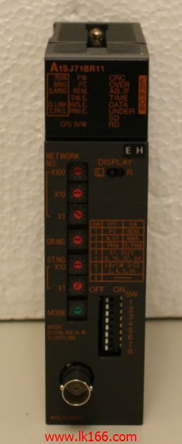
MITSUBISHI A1SJ71BR11 Network module
Brand:
MITSUBISHI
Name: Network module
Model: A1SJ71BR11
3C-2V/5C-2V coaxial cable between the single bus PC network (control station / common station) / remote I/O network (remote master).
The response time of PLC is the interval between the time of the change of the external output signal of the PLC and the time of the change of the external output signal which is controlled by it,
Lag time, this is the time constant of the input circuit,
The time constant of the output circuit, the arrangement of the user statement and the use of the instruction,
The cycle scan mode of PLC and the way of PLC to refresh the I/O and so on.
This phenomenon is called the I/O delay time effect.
Switch volume control is designed to,
According to the current input combination of the switch quantity and the history of the input sequence,
So that PLC generates the corresponding switching output,
In order to make the system work in a certain order.
So, sometimes also known as the order control.
And sequential control is divided into manual, semi-automatic or automatic.
And the control principle is decentralized, centralized and hybrid control three.
...More relevant models >>>>
Name: Network module
Model: A1SJ71BR11
3C-2V/5C-2V coaxial cable between the single bus PC network (control station / common station) / remote I/O network (remote master).
The response time of PLC is the interval between the time of the change of the external output signal of the PLC and the time of the change of the external output signal which is controlled by it,
Lag time, this is the time constant of the input circuit,
The time constant of the output circuit, the arrangement of the user statement and the use of the instruction,
The cycle scan mode of PLC and the way of PLC to refresh the I/O and so on.
This phenomenon is called the I/O delay time effect.
Switch volume control is designed to,
According to the current input combination of the switch quantity and the history of the input sequence,
So that PLC generates the corresponding switching output,
In order to make the system work in a certain order.
So, sometimes also known as the order control.
And sequential control is divided into manual, semi-automatic or automatic.
And the control principle is decentralized, centralized and hybrid control three.
Cable length: 0.055 meters.
Extending cable to connect CPU main substrate and extended substrate,
According to the model can provide different cable length,
If you need to connect the AnN type expansion substrate is required,
Selection of A1SC05NB (A1SC07NB) cable. Input and output points: 512 points MITSUBISHI A1SJ71BR11.
Input / output data points: 8192 points.
Program capacity: 28k.
Basic command processing speed (LD command) S:0 A1SJ71BR11075.
PLC in the program execution stage: according to the order of the user program order to store the order of each instruction,
After the corresponding operation and processing, the result is written to the output status register,
The contents of the output status register are changed with the execution of the program MITSUBISHI A1SJ71BR11.
Output refresh phase: when all instructions are executed,
The output status register is sent to the output latch in the output refresh stage,
And through a certain way (relay, transistor or transistor) output, drive the corresponding output equipment. A1SG60 is an empty cover that is used to plug in the unused I/O slot on the main board or on the extended board MITSUBISHI A1SJ71BR11.
A1SG60 is a reserved dummy module I/O point to PLC extended I/O system.
With the switch on the module can be set to retain the I/O point,
Can set 16 points, 32 points, 48 points and 64 points. Type of input: DC source.
Input points: 32 points.
Input voltage: 5/12.
Input current: 1.2/3.3mA.
Connection mode: terminal row.
Common common point: 32.
Functional block diagram language is a kind of PLC programming language, which is similar to digital logic circuit.
The function module is used to represent the function of the module,
Different function modules have different functions.
Functional module figure programming language features: functional block diagram programming language is characterized by a functional module for the unit,
Analysis and understanding of the controol scheme is simple and easy: function module is to use graphical form of expression,
Intuitive, for a digital logic circuit based on the design of the staff is very easy to master the programming;
Control system with complex scale and coomplex control logic,
Because the function module diagram can clearly express the function relation, the programming debugging time is greatly reduced A1SJ71BR11 A1SJ71BR11.
...More relevant models >>>>
 Last one:
  next one:
 Related download