
Home
>> Products
>> MITSUBISHI
>> A/QnA series PLC
>> High function module
>> MELSECNET/10 module
>> MITSUBISHI AJ72QBR15 Coaxial cable module
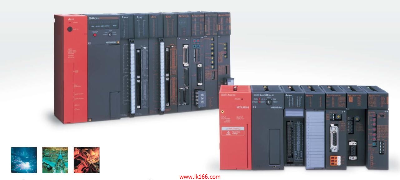
MITSUBISHI AJ72QBR15 Coaxial cable module
Brand:
MITSUBISHI
Name: Coaxial cable module
Model: AJ72QBR15
3C-2V/5C-2V coaxial cable.
Single bus.
Remote I/O network (remote control station).
How to choose MITSUBISHI PLC.
MITSUBISHI PLC options include the choice of MITSUBISHI PLC models, capacity, I/O module, power, etc..
MITSUBISHI PLC distribution I/O points and design MITSUBISHI PLC peripheral hardware circuit
Draw the I/O point of the PLC and the input / output device connection diagram or the corresponding table,
This part also can be carried out in second steps.
Design PLC peripheral hardware circuit.
Draw the electrical wiring diagram of the other parts of the system,
Including the main circuit and the control circuit does not enter the PLC, etc..
The electrical schematic diagram of the system composed of I/O PLC connection diagram and PLC peripheral electrical circuit diagram.
So far the system''s hardware electrical circuit has been determined.
...More relevant models >>>>
Name: Coaxial cable module
Model: AJ72QBR15
3C-2V/5C-2V coaxial cable.
Single bus.
Remote I/O network (remote control station).
How to choose MITSUBISHI PLC.
MITSUBISHI PLC options include the choice of MITSUBISHI PLC models, capacity, I/O module, power, etc..
MITSUBISHI PLC distribution I/O points and design MITSUBISHI PLC peripheral hardware circuit
Draw the I/O point of the PLC and the input / output device connection diagram or the corresponding table,
This part also can be carried out in second steps.
Design PLC peripheral hardware circuit.
Draw the electrical wiring diagram of the other parts of the system,
Including the main circuit and the control circuit does not enter the PLC, etc..
The electrical schematic diagram of the system composed of I/O PLC connection diagram and PLC peripheral electrical circuit diagram.
So far the system''s hardware electrical circuit has been determined.
Input and output points: 480 points.
Program capacity: 7K step.
Basic command processing speed: 4.4 ~ 5.6us.
Power supply: input DC5V output 2A DC24V/.
Modular: PLC is the basic components of a separate module.
Medium and large PLC used this way. Easy maintenance.
Relay output interface circuit of PLC
Working process: when the internal circuit output digital signal 1,
There is a current flowing through, the relay coil has a current, and then the normally open contact is closed,
Provide load current and voltage MITSUBISHI AJ72QBR15 AJ72QBR15
When the internal circuit outputs a digital signal 0, there is no current flowing through it,
The relay coil does not have a current, and the normally open contact is broken off,
A current or voltage that is disconnected from the load MITSUBISHI AJ72QBR15.
It is through the output interface circuit to the internal digital circuit into a signal to make the load action or not action.
User program storage capacity: it is a measure of how much the user application can store the number of indicators.
Usually in words or K words as units. 16 bit binary number is a word,
Every 1024 words are 1K words MITSUBISHI AJ72QBR15. PLC to store instructions and data in words.
General logical operation instructions each account for 1 words. Timer / counter,
Shift instruction accounted for 2 words. Data operation instructions for 2~4.
Program 2 channel connection, AnCPU/QnACPU use.
MITSUBISHI PLC detection, fault diagnosis and display and other procedures.
These procedures are relatively independent, generally in the basic completion of the program design and then add.
MITSUBISHI PLC protection and chain procedures.
Protection and chain is an indispensable part of the program, must be carefully considered.
It can avoid the control logic confusion caused by illegal operations. Output points: 16 points.
Voltage: DC24V/AC240V, 2A/1 point, 8A/1 public end.
Output type: relay output.
Response time: 12ms.
8 point /1 a public side.
20 point terminal station.
The number of I/O thyristor DC motor control required tube DC motor speed control system is the main form of DC speed regulation,
The thyristor rectifier unit is used to supply power to the DC motor.
PLC control of the DC drive system, the input of the PLC in addition to the main signal outside the signal,
We need to consider the switching signal, the fault signal transmission device, brake signal and fan fault signal.
The output of the PLC mainly consider the speed command signal positive 1~3 level, 1~3 level, allowing reverse switching signal and brake open signal etc..
In general, a reversible DC drive system controlled by PLC is approximately 12 input points and 8 output points,
An irreversible DC drive system requires 9 inputs and 6 output points.
MITSUBISHI PLC is the main product in the production of MITSUBISHI motor in Dalian.
It uses a kind of programmable memory for its internal storage procedures,
Execute logic operation, sequence control, timing, counting and arithmetic operations, user oriented instruction,
And through digital or analog input / output control of various types of machinery or production process.
Control solenoid valve required I/O points by the action principle of the solenoid valve caan be known,
A single coil solenoid valve with PLC control to 2 input and 1 output,
A double coil solenoid valve requires 3 inputs and 2 outputs,
A button needs an input; a light sensitive switch needs 4 or 2 inputs,
A signal lamp needs 1 output, band switch,
Several bands are required for several inputs,
In general, a variety of position switches are required to take up 2 input points AJ72QBR15 AJ72QBR15.
...More relevant models >>>>
 Last one: MITSUBISHI Coaxial cable module AJ71QBR11
 next one: MITSUBISHI Coaxial cable module AJ71QLR21
Related download