
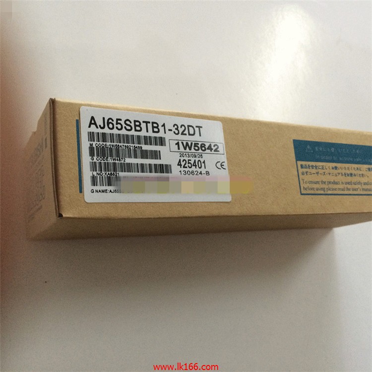
AJ65SBTB1-32DT DC input / transistor output module MITSUBISHI AJ65SBTB1-32DT
DC input points: 2 points.
Input voltage and current: 7mA, DC24V.
Input response time: 10ms.
2 point /1 a public side.
Positive / negative sharing.
Output points: 2 points.
Output voltage and current: DC24V/AC240V, 2A/1 point, 4A/1 common end.
Output response time: 2ms AJ65SBTB1-32DT.
2 point /1 a public side.
Output form: reelay.
16 point terminal station.
MITSUBISHI PLC protection and chain procedures.
Protection and chain is an indispensable part of the program, must be carefully considered AJ65SBTB1-32DT.
It can avoid the control logic confusion caused by illegal operations.
MITSUBISHI PLC initialization procedure. After MITSUBISHI PLC on power, the general need to do some of the initial operation,
In order to start making necessary preparations, to avoid the wrong operation of the system AJ65SBTB1-32DT.
The main contents of the initialization program are: to some data area, counter and so on,
Data needed to restore some of the data area,
Set or reset some relays,
For some initial state display, etc..
MITSUBISHI PLC program simulation debugging
The basic idea of program simulation debugging is,
In order to facilitate the form of simulation to generate the actual state of the scene,
Create the necessary environmental conditions for the operation of the program MITSUBISHI AJ65SBTB1-32DT.
Depending on the way the field signals are generated,
The simulation debugging has two forms of hardware simulation and software simulation MITSUBISHI AJ65SBTB1-32DT. Analog channel: 16 channels.
Input / output (resolution): 0 ~ 4000.
Conversion speed: 100ms/16 channel.
Analog module installation.
Power supply: AC85 ~ 132V.
According to the control requirements of the system, using the appropriate design method to design MITSUBISHI PLC program MITSUBISHI AJ65SBTB1-32DT.
Procedures to meet the requirements of system control as the main line,
Write one by one to achieve the control function or the sub task of the program,
Gradually improve the functions specified by the system.
MITSUBISHI PLC detection, fault diagnosis and display and other procedures.
These procedures are relatively independent, generally in the basic completion of the program design and then add.
Hardware simulation method is to use a number of hardware equipment to simulate the generation of the signal,
The signals are connected to the input end of the PLC system in a hard wired way, and the timeliness is strong.
Software simulation method is in the MITSUBISHI PLC in the preparation of a set of simulation program,
The simulation provides the field signal, which is simple and easy to operate, but it is not easy to guarantee the timeliness.
Simulation of the process of debugging, debugging method can be used to segment, and the monitoring function of programmer.
Input type: DC input, positive common end.
Input points: 16 points.
Enter the response time: 1.5ms the following.
Rated input voltage / current: DC24V/7mA.
Output form: transistor output, leakage type.
Output points: 16 points.
OFF leakage current: 0.25mA.
Output protection function.
Rated load voltage / current: DC24V/0.5A.
External connection: 1 line /1 line type.
According to the external connection mode and the external equipment input and output specifications,
Choose from a rich product lineup AJ65SBTB1-32DT.
Finger protection through the upper part of the terminal,
The human body will not be exposed to live parts,
Therefore, the terminal station type remote I/O module can be directly mounted to the machine tool.