
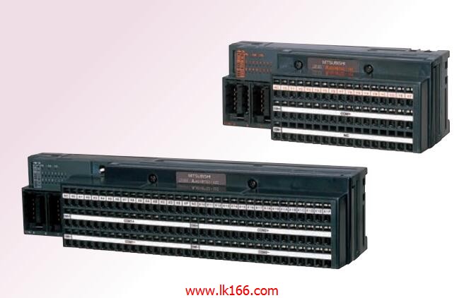
AJ65VBTS32-32DT MITSUBISHI Spring clip terminal type DC input / transistor output module MITSUBISHI AJ65VBTS32-32DT
3C-2V/5C-2V coaxial cable.
Double loop.
PC inter network (management station / common station) / remote I/O network (remote control station).
How to choose MITSUBISHI PLC.
MITSUBISHI PLC options include the choice of MITSUBISHI PLC models, capacity, I/O module, power, etc..
MITSUBISHI PLC distribution I/O points and design MITSUBISHI PLC peripheral hardwarre circuit
Draw the I/O point of the PLC and the input / output device connection diagram or the corresponding table,
This part also can be carried out in second steps AJ65VBTS32-32DT AJ65VBTS32-32DT.
Design PLC peripheral hardware circuit.
Draw the electrical wiring diagram of the other parts of the system,
Including the main circuit and the control circuit does not enter the PLC, etc..
The electrical schematic diagram of the system composed of I/O PLC connection diagram and PLC peripheral electrical circuit diagram AJ65VBTS32-32DT.
So far the system''s hardware electrical circuit has been determined. Bus connector conversion cable package
Input type: DC input, positive common end.
Input points: 16 points.
Enter the response time: 1 MITSUBISHI AJ65VBTS32-32DT.5ms the following.
Rated input voltage / current: DC24V/5mA.
Output form: transistor output, leakage type.
Output points: 16 points.
OFF leakage current: 0.1mA.
Output protection function: No.
Rated load voltage / current: DC12V/DC24V/0.5A.
External connection: 3 line /2 line type MITSUBISHI AJ65VBTS32-32DT.
Spring clip terminal.
Do not need to be tightened further or locked with screws, which can reduce the working hours of wiring.
Using 2 pieces of structure of the terminal units, maintenance can be maintained in the same line under the condition of the replacement module MITSUBISHI AJ65VBTS32-32DT.
When installing the module can choose to use the DIN guide rail or screw mounting.
Can be used for the 3 wire sensor input wiring. 8 slots.
Power supply unit.
QnAS series unit installation.
High speed access.
I/O points is an important indicator of PLC.
Reasonable selection of I/O points can not only satisfy the control requirements of the system,
And the total investment of the system is the lowest.
The input and output points and types of PLC should be determined according to the analog quantity and switch quantity of the controlled object,
Generally an input / output element to take up an input / output point.
Taking into account the future adjustment and expansion,
In general should be estimated on the total number of points plus the amount of spare 20%~30%.
When the programmer input programinto the user program memory,
Then CPU according to the function of the system (the system program memory to explain the compiler),
Translate the user program into PLC internally recognized by the user to compile the program.
Relay output interface circuit of PLC
Working process: when the internal circuit output digital signal 1,
There is a current flowing through, the relay coil has a current, and then the normally open contact is closed,
Provide load current and voltage.
When the internal circuit outputs a digital signal 0, there is no current flowing through it,
The relay coil does not have a current, and the normally open contact is broken off,
A current or voltage that is disconnected from the load AJ65VBTS32-32DT.
It is through the output interface circuit to the internal digital circuit into a signal to make the load action or not action.