
AJ65SBTW4-16DT Design control cabinet and the operating table and other parts of the electrical wiring diagram and wiring diagram MITSUBISHI AJ65SBTW4-16DT
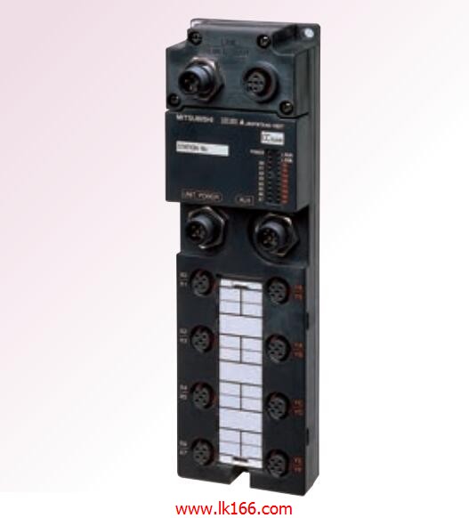
Output type: relay.
Output points: 16 points.
Load voltage: AC240/DC24.
Load current: 2A.
Connection mode: terminal row.
Common public end points: 8.
Sequential function flow chart language is designed to satisfy the sequential logic control.
The process of sequential process action is divided into steps and transformation conditions,
According to the transfer condition, the control system is distributed in the function flow sequence,
Step by step according to the sequence of actions AJ65SBTW4-16DT AJ65SBTW4-16DT.
Each step represents a control function, represented by the box.
In the box, the ladder logic is used to complete the task of the corresponding control function.
This programming language makes the program structure clear and easy to read and maintain,
Greatly reduce the programming workload, shorten the programming and debugging time AJ65SBTW4-16DT.
Used in the system of the size of the school, procedures for more complex occasions.
Sequence function flow chart programming language features: to function as the main line, in accordance with the functional flow of the order of distribution, clear, easy to understand the user program,
Avoid the defect of ladder diagram or other languages,
At the same time, the use of ladder language to avoid the use of ladder programming,
Due to the complicated mechanical interlock, the structure of the user program is complex and difficult to understand,
User program scan time is also greatly reduced MITSUBISHI AJ65SBTW4-16DT MITSUBISHI AJ65SBTW4-16DT. Program memory capacity 14K.
Input and output points to the maximum 512 points.
A scan cycle of PLC must pass through three stages: input sampling, program execution and output refresh MITSUBISHI AJ65SBTW4-16DT.
PLC in the input sampling phase: first of all, in order to scan the sequence of all existing input latches in the input terminal of the state or input data read,
And write it into the corresponding input status register,
Refresh the input, then close the input port, enter the program execution stage.
Enter 8 points: 24VDC.
4 wire type.
Response time: 1.5ms.
Output 8 points: 24VDC.
Transistor output.
Waterproof connector type.
MITSUBISHI PLC hardware implementation
Hardware implementation is mainly for the control cabinet and other hardware design and field construction.
Design control cabinet and the operating table and other parts of the electrical wiring diagram and wiring diagram.
Electrical interconnection diagram of each part of the design system.
According to the construction drawings of the site wiring, and carry out a detailed inspection.
Because the program design and hardware implementation can be carried out at the same time,
So the design cycle of the MITSUBISHI PLC control system can be greatly reduced.
MITSUBISHI PLC online debugging.
On-line debugging is the process that will through the simulation debugging to further carry on the on-line unification to adjust.
On-line debugging process should be step by step,
From MITSUBISHI PLC only connected to the input device, and thhen connect the output device, and then connect to the actual load and so on and so on step by step AJ65SBTW4-16DT.
If you do not meet the requirements, the hardware and procedures for adjustment.
Usually only need to modify the part of the program can be.