
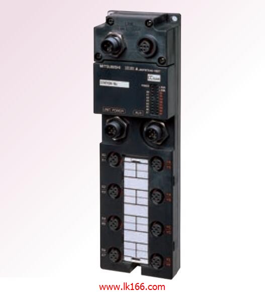
AJ65SBTW4-16DT Waterproof connector type DC input / transistor output module MITSUBISHI AJ65SBTW4-16DT
Data format: RTU.
Data bits: 8.
A1SJ71UC24-R2-S2 and A1SJ71UC24-R4-S2 allow the Ans series PLC to be connected to the MODBUS network,
As the network from the station, and in accordance with the instructions of the main station of the CPU Ans user storage area for data reading / writing AJ65SBTW4-16DT.
In addition to supporting the MODBUS protocol, these components also support the standard dedicated communication protocol for A1SJ71UC24 components.
This feature makes the main station of the data acquisition and control with more flexibility AJ65SBTW4-16DT.
Support MODBUS slave station protocol.
Supports 1 to 21 function code.
Two transmission modes: RTU or ASCII. For A6TBXY36/A6TBXY54/A6TBX70E (common cathode; drain type) long 0.5m.
Enter 8 points: 24VDC.
4 wire type.
Response time: 1 AJ65SBTW4-16DT.5ms.
Output 8 points: 24VDC.
Transistor output.
Waterproof connector type.
MITSUBISHI PLC hardware implementation
Hardware implementation is mainly for the control cabinet and other hardware design and field construction.
Design control cabinet and the operating table and other parts of the electrical wiring diagram and wiring diagram MITSUBISHI AJ65SBTW4-16DT.
Electrical interconnection diagram of each part of the design system.
According to the construction drawings of the site wiring, and carry out a detailed inspection.
Because the program design and hardware implementation can be carried out at the same time,
So the design cycle of the MITSUBISHI PLC control system can be greatly reduced MITSUBISHI AJ65SBTW4-16DT.
MITSUBISHI PLC online debugging.
On-line debugging is the process that will through the simulation debugging to further carry on the on-line unification to adjust MITSUBISHI AJ65SBTW4-16DT.
On-line debugging process should be step by step,
From MITSUBISHI PLC only connected to the input device, and then connect the output device, and then connect to the actual load and so on and so on step by step.
If you do not meet the requirements, the hardware and procedures for adjustment.
Usually only need to modify the part of the program can be. Cable length: 0.45 meters
Extending cable to connect CPU main substrate and extended substrate,
According to the model can provide different cable length,
If you need to connect the AnN type expansion substrate is required,
Selection of A1SC05NB (A1SC07NB) cable. Cable for unit load.
Length: 80mm.
Input / output unit standard equipment.
MITSUBISHI PLC program simulation debugging
The basic idea of program simulation debugging is,
In order to facilitate the form of simulation to generate the actual statee of the scene,
Create the necessary environmental conditions for the operation of the program AJ65SBTW4-16DT.
Depending on the way the field signals are generated,
The simulation debugging has two forms of hardware simulation and software simulation.